Communications of the ACM
How Does a Pantograph Work?

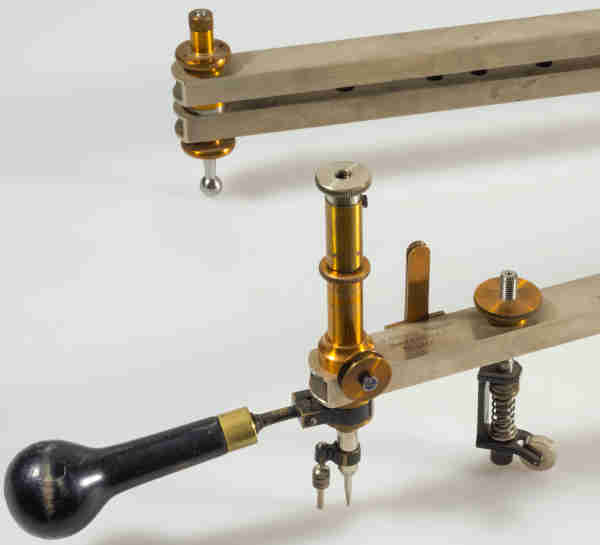
Pantographs (see Figs. 1–2) have been widely used for centuries; for example, in surveying and embroidery. With these devices, drawings can be enlarged and reduced.
Christoph Scheiner from Germany (1603) is considered the inventor. However, Heron of Alexandria (1st century) had already designed a pantograph, which, however, worked with a cogwheel gear.
|
|
Fig. 1: Pantograph.
The German company Ott in Kemptenwas one of the most
important manufacturers of mathematical instruments.
Credit: Vermessungsamt, Aarau, Switzerland

Fig. 2: Pantograph.
With the traveling stylus, one traces the perimeter of a drawing.
The drawing pen reproduces the figure simultaneously.
Credit: Historisches Museum Thurgau, Schloss Frauenfeld, Switzerland
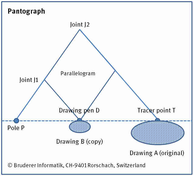
The analog instrument (see Fig. 3) is comprised of a movable linkage of wood, metal or plastic. It embodies a parallelogram. The opposite interior angles are equal and the sum of two adjacent interior angles is 180°. The two diagonals are halved. The rods are connected via articulated joints. The pole (fixed pivot), tracer point, and drawing pen all lie on a straight line.

Fig. 3: Pantograph.
To reduce drawing A, the pantograph is fixed at the pole P. With the adjustable bars, the given ratio is defined.
With the tracer point T the outline of drawing A is traced. The drawing pen D produces a similar figure in the chosen scale.
Exchanging the drawing pen and the tracer point enlarges the figure.
PJ1 : PJ2 = PD : PT
PJ2 : PJ1 = PT : PD
PJ1 : J1J2 = PD : DT
PJ2 : J1J2 = PT : DT.
Example
PJ1 : PJ2 = 6 : 12 enlargement by the factor two (to 200 %)
PJ2 : PJ1 = 12 : 6 reduction by the factor two (to 50 %).
Note
The pantograph of Coradi (Zurich) with a scale length of 65cm provides for enlargement and reduction ratios from 0.05 to 0.8:
1/20, 1/12, 1/10, 1/8, 1/6, 1/5, ¼, 1/3, 2/5, 2/3, ¾, 4/5, ½, 1/1, 5/4, 4/3, 3/5, 3/8, 2/3.
References
Bruderer, H.: Meilensteine der Rechentechnik, De Gruyter Oldenbourg, Berlin/Boston, 2nd edition 2018, 2 volumes, 1600 pages, https://www.degruyter.com/view/product/480555 and https://www.degruyter.com/view/product/503373
Bruderer, H.: Milestones in Analog and Digital Computing, Springer Nature Switzerland AG, Cham, 3rd edition 2020, 2 volumes, ca. 2000 pages, https://www.springer.com/de/book/9783030409739
Coradi, G.: Mathematisch-mechanisches Institut G. Coradi, Zürich. Verzeichnis über mathematische Präzisions-Instrumente, Zürich 1915, 48 pages
Drachmann, A. G.: The mechanical technology of Greek and Roman antiquity. A study of literary sources, Ejnar Munksgaard, Copenhagen 1963, 220 pages
Jordan, W., Eggert, O., and Berroth, A.: Handbuch der Vermessungstechnik, volume 2: Feld- und Landmessung, J. B. Metzlersche Verlagsbuchhandlung, Stuttgart, 10th edition 1950, xvi, 640 pages
Kronauer, J. H.: Goldschmid's schwebender Pantograph, in: Schweizerische polytechnische Zeitschrift, volume 9, 1864, issue 5, pages 157–158
von Braunmühl, A.: Christoph Scheiner als Mathematiker, Physiker und Astronom, Buchnersche Verlagsbuchhandlung, Bamberg 1891, vi, 92 pages.
Herbert Bruderer is a retired lecturer in didactics of computer science at ETH Zürich. More recently, he has been an historian of technology. bruderer@retired.ethz.ch, herbert.bruderer@bluewin.
No entries found